Here’s a run-through of building my latest 5″ quad. I used MEPS motors, ESC and FC mounted on an Armattan Marmotte frame with Caddx Walksnail digital VTX, resulting in a stylish drone that’s small enough to fit in a backpack, yet powerful enough to fly in the mountains with the weight of a GoPro.
Components
Here are the components I chose for this quad. The pairing of motors to the style of the flying and type of battery is important. The MEPS 2306 2450KV motors pair nicely with the Marmotte frame and 4S LIPO battery use. The MEPS 20 x 20 mm stacked 45A ESC & F7 FC fit perfectly in the space-limited Marmotte 5″ frame. The challenge is the Avatar HD unit, with a Marmotte-incompatible 25 x 25 mm mount. This can be overcome with 3D-printed mounts.
| Part | Manufacturer |
|---|---|
| Frame | Armattan Marmotte 5″ |
| Flight Controller | MEPS FPV Flight Controller SPACE SZ F7 Mini (20 x 20 mm mount) |
| ESC | MEPS MINI SZ45A 6S 4IN1 ESC (20 x 20 mm mount) XT60 connector (male) for power (included with ESC) |
| Motors | MEPS FPV Brushless Motor SZ2306 for 5-Inch Freestyle Drone / 2450KV / Cool Grey |
| VTX | Walksnail Avatar HD (25.5 x 25.5 mm mount) + 3D-printed component mount + 3D-printed camera shims + 3D-printed antenna/power mount (Avatar v1 or Avatar v2) |
| RX | TBS Crossfire Nano RX + 3D-printed tray to hold the RX |
| GPS | iFlight M8Q-5883 GPS Module VIFLY GPS Mate (with buzzer) + 3D-printed holder for mounting on battery strap |
| Buzzer | Included in VIFLY GPS Mate |
| Props | Azure Race/Freestyle 5″ 5140 |
| Battery | 4S 2400MAH 120C 35.52WH |
| Camera | GoPro Hero 11 Mini |
The weight of the drone (without battery & GoPro) is 345g. With the battery, it comes to 625g, and with a battery and GoPro Mini, 775 grams.
Building
My first step is drawing out a wiring diagram to ensure all the components can connect up. It prevents soldering & voltage mismatches when constructing, and makes it easy to determine the Betaflight UART configuration. Previous builds with analog VTXs required a lot more soldering. The MEPs flight controller has JST-SH connectors to make it easy to connect ESC & VTX components together. Only the RX, GPS and buzzer require soldering to the FC.

Now to assembling the basic frame, adding the motors and planning out on the drone frame where all the components will go. The Marmotte frame is a pretty tight fit, allowing a 20 x 20 mm or 30 x 30 mm stack, and then space on either side to squeeze in a VTX and other components.

The most optimal layout for a 20 x 20 mm FC/ESC stack is the center stack, as the front 20 x 20 mm is constrained by the camera cage. The Walksnail Avatar HD VTX can be placed at the rear with a 3D-printed mount to cater for the 25 x 25 mm to 30 x 30 mm inconsistency.
The focus is now on the power hub of the drone. The MEPS ESC comes with several helpful extras to aid using the ESC – an XT60 male pigtail, ESC wiring connectors and anti-vibration grommets, as shown below.

The ESC is mounted in the center of the frame, allowing sufficient height for the motor cables to pass underneath, and to prevent the ESC touching the carbon-fibre frame. The yellow grommets hold the ESC in position, with extenders for mounting the FC above it. The ESC is really slim, keeping the component nicely tucked within the frame cage.

A fiddly part of the build is connecting the motor cables to the ESC. I use a plastic covering for the motor cabling to keep the wires tidy, and to keep the wires in the frame of the drone, run the cables under the ESC. It looks tidier and prevents wires being torn out on any crashes. The motor assignment & rotation can be configured via software if the physical motor connections do not correspond to the ESC motor numbering. For the XT60 battery connector, I will hold it in place at the rear of the frame with a 3D-printed mount.

Moving on to the VTX. The mounting of the Avatar HD VTX is critical to understanding the space left over for wiring and other components. Owing to the mismatch in mounting dimensions, a tray mount is required to secure it to the rear of the frame. In addition, an extended 3D-printed battery/antenna holder can be used for holding the two antennas in a V-shape out the rear of the drone. The 4 x M2 bolts & nuts are the ones provided with the VTX.


The VTX can be secured in the frame with the conversion mount and the antenna/XT60 mount on the rear of the drone.

To avoid seeing the camera cage, two shims are used to secure the camera in the Marmotte FPV camera cage (see Walksnail Avatar Micro to Mini Camera Adapter for the Armattan Marmotte). Like the tray, the nuts & bolts provided with the Avatar HD can be used to secure shims.
The drone now has the VTX installed, with the camera cage secured at the front. It’s starting to look like a quad. I love the way the motor cables can be soldered beneath the MEPS ESC, preventing wiring snags and improving the aesthetics.

Time to move onto installing the FC. I’m using a MEPS flight controller, which pairs very easily with the mounted MEPS ESC and a digital VTX. A nice selection of JST connectors are provided, as one can see in the diagram below. I will use the ESC connector, and combine with the Walksnail JST connector, which is wire-compatible with the FC digital VTX input.

Before installing the flight controller in the drone, I usually wire up the RX, as it’s easier to solder off the drone frame. This is especially the case for the 20 x 20 mm flight controllers – in order to squeeze in all the UARTs, the solder pads are double layered and tiny!

After soldering the RX in place, it’s time to stack the FC and connect it to the ESC and VTX.

The drone is now on the way to being operational! The Betaflight settings can be configured, the motor directions defined, and the RX modes assigned. The VTX OSD layout can be configured and tested with the FPV goggles.

The Avatar HD (version 1) unit generates large interference for GPS units. For this reason, I will mount the GPS unit on top of the battery. I will also use a Vifly GPS Mate, firstly to allow GPS lock prior to powering the drone (no wasting LIPO battery time for lock), and secondly as it incorporates a battery an buzzer, so if the battery is detached, one can hear the drone scream in the woods.

Now that all the components are connected, the Betaflight configuration can be fully applied and reviewed. The full configuration of the quad is beyond the scope of this post (there are lots of online Betaflight setup tutorials), but I will mention the points relevant to this particular build and FC/ESC set-up.
Firstly, ensure you have the latest Betaflight Configurator and flash the drone with the latest firmware. For the MEPS FC that I’m using, it requires the TMOTORF7 firmware (auto-detect finds it). Based upon the hardware I have for this build, I ensured CRSF protocol, GPS, PIN IO, OSD (HD) and VTX were enabled. The PIN IO setting is required for VTX pit mode management. The motor protocol for the MEPS ESC is DSHOT.


In the Betaflight “Ports” tab, the ports need to be configured to UARTs chosen for the hardware. The UART port settings align with the UARTs that the components are wired to. As per the wiring diagram at the top of this post, I have the following pairings:
- UART1 – Avatar Walksnail VTX
- UART2 – nothing
- UART3 – GPS
- UART4 – ESC
- UART5 – RX (crossfire)
One feature the MEPS FC has – and requires configuring – is a pit mode for the VTX. This feature prevents the VTX from being powered until a software switch is enabled. In the CLI execute the following command:
set pinio_box = 39,0,0,0
save
In the Betaflight Modes associate “VTX PIT MODE” with a switch on your transmitter – for example the ARM AUX range. Only when armed will the VTX switch on. Following this, one configures Crossfire, the GPS, the telemetry output and the modes as one requires. The drone can now be bench tested to ensure all the modes are working correctly, the motors are spinning in the correct directions, and the OSD output is configured.
Ready To Fly
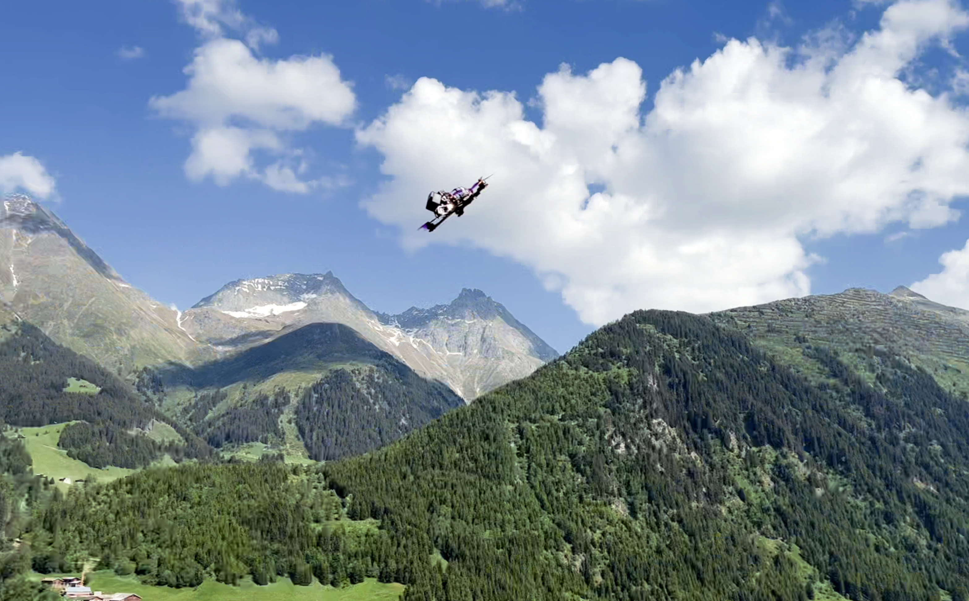
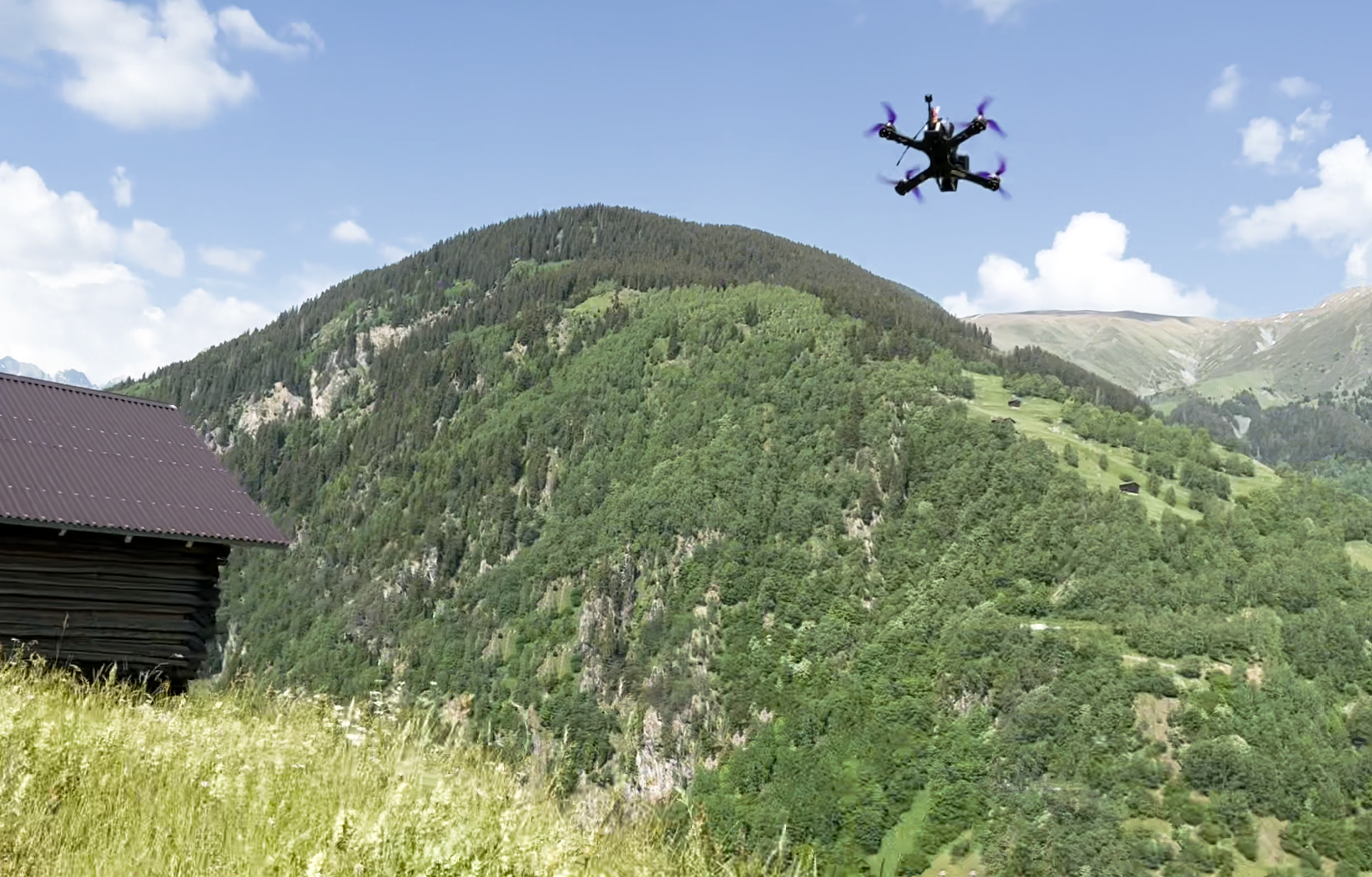
Here are a couple of photographs of the drone, ready for a test flight. The MEPs motors make the drone look great, and the components all fit together really well for a solid and stable build.


Flying
With stock PIDs the quad flies with a lot of acceleration and speed. I tuned the quad to be a little more smooth-flying for cinematic flights. It cruises nicely at 60 kph, and reaches 110 kph with ease. All-in-all, a great drone for taking in a backpack for flights in the mountains.